Identify Components Quickly With One Handy Device
Identify and measure discrete components in one shot
Have you ever had trouble identifying a component on a circuit board by sight? It can be confusing. Many types of components come in the same packages. A power transistor, MOSFET, and voltage regulator can all look the same. A friend turned me on to a little component checker that can really help identify mystery components. It also measures relevant values for the component. It’s so handy that it’s competing with my multi-meter as the first thing I grab when I’m looking over a circuit board I’m trying to repair. It’s helped me out so I’m sharing it with you so that it can help you out, too.
Resistors are measured with ohmmeters, capacitors with capacitance meters, coils with inductance meters, diodes with diode-checkers, and transistors with transistor-checkers – if you know the pinout and channel. Most or all of this is built into common multi-meters. But you have to know what you’re testing, and then select the right function to get the right measurement. This component tester avoids all of that. Just hook it up to the leads and it will identify the component and measure it in one action.

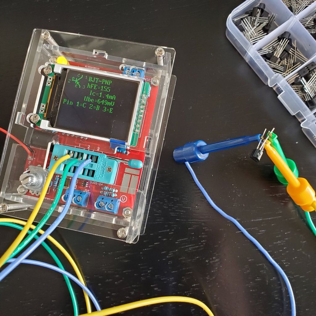
The tester has a ZIF socket on it which really uses only three connection points. The socket makes it easier to get components into it. If the component has two leads, use any two adjacent connections. You lock the leads of the component into the socket and press the button on the tester. The color LCD display comes on, runs through a little self-check, then tests and measures the component and displays the result on the screen. After a few seconds it turns itself off.
It can identify components including resistors, capacitors, diodes, and various transistors such as BJT, JFET, MOSFET, dual-diodes, SCR’s, and thyristors. Most discrete components you will encounter are covered.
It can be ordered assembled or as a kit you build yourself. I thought I ordered the assembled version, but the kit showed up instead. No problem. It’s a two-sided PCB with all through-hole components to assemble. The three or four surface mount components are already mounted on the PCB when you get the kit. Like any board, I find it helps to assemble it in order of height profile of components. Resistors and diodes first, then capacitors, sockets, connectors, and switches. But use whatever approach you’ve developed for yourself of course.
The kit comes with standard 5% tolerance resistors. For the measurement part of the circuit, the more precise the resistors are, the more precise your measurements will be I believe. I measured all the resistors and ended up swapping one out because it seemed out of tolerance. You could use 1% resistors if you have them.
The device uses an ATMega328 microcontroller to identify components and measure them. Before you put the microcontroller in the DIP socket, connect a battery, press the button, and measure the supply voltage to the microcontroller at pin 7. Make sure it’s not too high. Then unplug the battery, insert the microcontroller and mount the display. Plug it back in and press the button, it should be working.
The documentation for the tester doesn’t come with it. You have to dig around to find it. The only links I could find were on EEVblog Electronics Community Forum. I thought I’d repeat those links here in an effort to make them a little easier to find [all PDF downloads from EEVblog].
- KKMoon Multifunctional Meter/Generator User Manual
- KKMoon Multifunctional Meter/Generator Schematic
- KKMoon Multifunctional Meter/Generator Assembly Instructions
I decided to fashion some leads for the tester. I leave these in the ZIF socket and use them to hook onto components. That way I can desolder one or two leads of the component and test it while it’s still in the board. You can also find a plastic case for it to help protect it.
This unit doesn’t just identify components, it also can serve as a signal generator. I haven’t tried that capability, so I’m not sure about load limitations, or accuracy of the signal. According to the manufacturer, it will generate frequencies from 1Hz to 2MHz. The options I see in the menu are from 10Hz to 1GHz. and do PWM from 1% to 99%. There are several other mysterious functions built into it, which I have yet to explore. Just for simply identifying a component and measuring it, this is worth having. If the rest works, all the better!
This certainly isn’t the only one of these devices out there. There are several multi-function component testers out there. This is the one I got, and I’m happy with it for under $30. If you use another one, like either of these, let me know if they work as well.


I’m curious if anyone has tried the oscilloscope kit which is similar to this? Is it good enough to give you a decent impression of what’s happening?

Happy testing!