Pi Pico Time-of-Flight Project in Arduino IDE
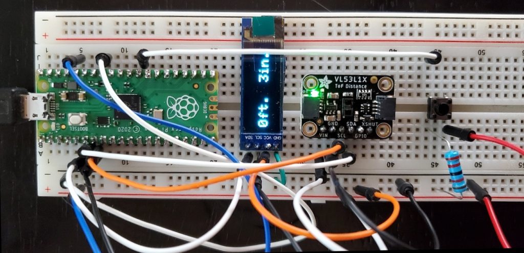
Time-of-Flight sensors are great for DIY electronics projects because they offer more accuracy that can be achieved using ultrasonic distance sensors. This project uses a Raspberry Pi Pico to interface with a laser-based time-of-flight sensor. It displays the sensor’s measurements on a small OLED display.
Time-of-Flight sensors are great for DIY electronics projects because they offer more accuracy that can be achieved using ultrasonic distance sensors. This project uses a Raspberry Pi Pico to interface with a laser-based time-of-flight sensor. It displays the sensor’s measurements on a small OLED display. In parts, this project is less than $25. You could add a battery, power switch, and 3D printed case and have a handy tool. The code is written in C using the Arduino IDE.
Using Raspberry Pi Pico with Arduino IDE
Adding Pico support to the Arduino IDE is straightforward thanks to the arduino-pico project on Github from Earle Philhower. Adding Pico support is like adding support for any other board.
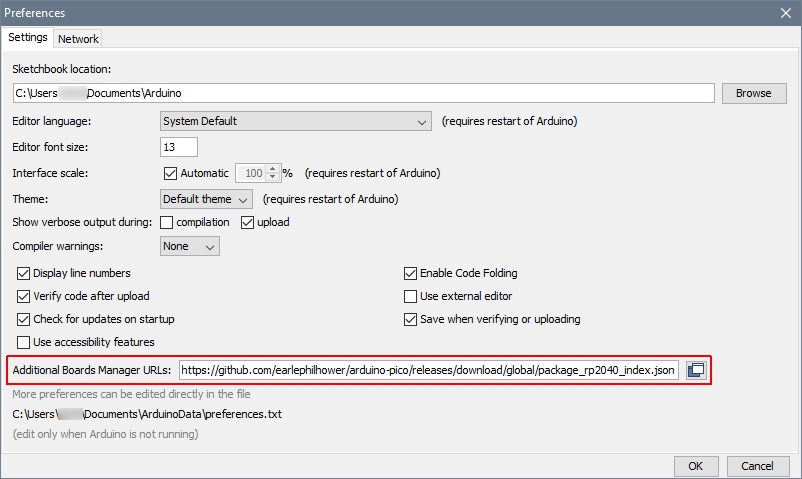
- In Arduino IDE, open File>Preferences. In the Additional Boards Manager URLs field, add the following URL. If you have other URLs in this field, leave them there, go to the end of the line, add a comma, and then this URL:
- Click OK to close the dialog.
- Open Tools>Board>Board Manager…, search for “pi pico” and install the “Raspberry Pi Pico/RP2040” board.
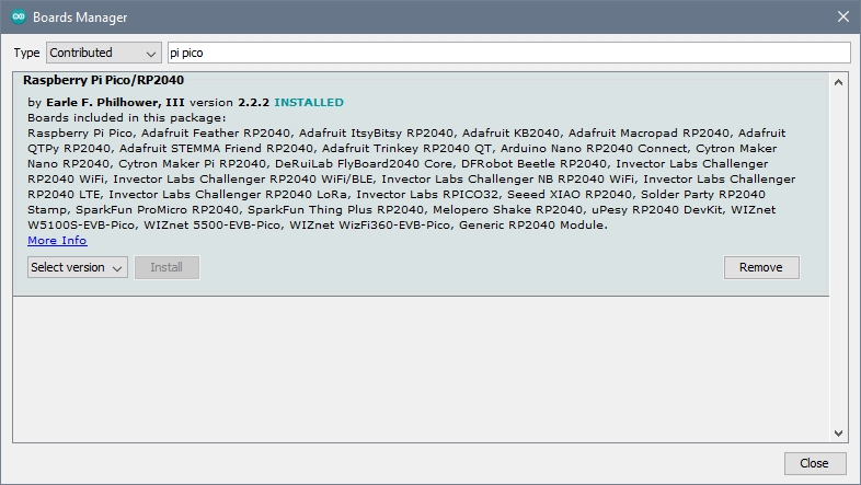
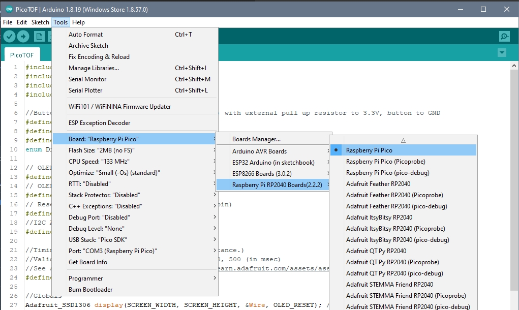
- Close the Boards Manager and from Tools>Board you should be able to select “Raspberry Pi RP2040 Boards > Raspberry Pi Pico”.
That’s all it takes. The arduino-pico board interface allows for a lot of functionality. Check out the documentation at https://arduino-pico.readthedocs.io/en/latest/index.html when you get a chance to see how you can leverage the serious power packed into the Pico.
A Couple of Quirks
The first time you connect the Pico to the PC, hold down the BOOTSEL button on the Pico as you plug in the USB cable. In fact, you may need to do this occasionally. There is a note on uploading sketches in the documentation discussing this.
Another easily-overlooked note in the documentation advises Windows users to use the Arduino IDE version on the Arduino.cc Downloads page, not the version in from Windows Store. Apparently the Store version has problems connecting to the device via the USB port. I tried both versions, and they both have intermittent problems. The direct download version may have them less often. I’ve tried holding the BOOTSEL button while plugging in the board, restarting the Arduino IDE, and resetting the board by pulling the RUN pin to ground to solve the issue. Some combination of those usually works. And sometimes the IDE says it encountered an error opening the COM port, but the sketch is uploaded anyway. Your mileage may vary.
Time of Flight Sensor
This project uses the Adafruit VL53L1X laser time-of-flight sensor. It has a range of 30mm to 4000mm. There are other options available at essentially or exactly the same price with distance range capabilities from 1mm to 6000mm. Aside from the supporting software library, these would work the same as the one I’m using. They use an I2C interface, and the Adafruit board includes level shifters to make the native 2.8 volt requirement interoperable with 3 to 5 volt devices.
Connections
Connect the Adafruit VL53L1X sensor board to the Pico:
| Sensor Board Pin | Pico Pin |
|---|---|
| GND | Any GND pin, like physical pin 33 |
| VIN | 3V3 OUT, physical pin 36 |
| SDA | I2C0SDA/GP4/Physical pin 6 (see note below) |
| SCL | I2C0SCL/GP5/Physicla pin 7 (see note below) |
| GPIO | No connect – this is an interrupt output, not used in this project |
| XSHUT | No connect – this is an active low signal to shut the sensor off, not used in this project |
Note on the I2C pins: The I2C buses are available on many pins. I found that using the standard Wire library without specifying the SDA and SCL pins, these are the pins the device was using. If you use the TwoWire libray, you can specify any pins you like.
Software
In the Arduino IDE, Select Tools>Manage Libraries…, and install the “Adafruit VL53L1X” library.
In addition to the library, we have the option of picking a value for one software setting called the Timing Budget. Increasing the Timing Budget value increases the range and accuracy of the sensor, and also increases power consumption. The possible values (from ST) are 20, 33, 50, 100, 200, and 500 milliseconds. Adafruit uses 50 in their example code, which I used in this project. Feel free to experiment with higher values if you need consistent millimeter accuracy.
Display
I chose a 0.91 inch, 128×32 pixel OLED monochrome display simply because it’s an I2C interface, I didn’t have a lot of information to display, and I have a box of them within arm’s reach.
Software
The display linked uses an SSD1306 controller, and again I turned to Adafruit for software libraries. For this display, install the Adafruit SSD1306 library, and its dependency the Adafruit GFX Library.
Connections
Connect Power, Ground, SDA, and SCL of the display to the same pins of the Pico as the time-of-flight sensor in the table above.
A Display Mode Button
The challenge with the display is that it’s small. I want to display the distance in both metric and imperial systems. Two lines of text on this display will fit, but are hard to read. Once I had it working, I decided to add “display modes” of Both, Metric, and Imperial. In Both mode, two lines of text are displayed, showing the distance both ways. In Metric and Imperial mode, one larger line of text is displayed showing the distance only in the appropriate system.
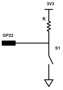
This means adding a button to cycle through the three display modes. You can use any GPIO pin to connect the button. I used GP22 (physical pin 29). I used a pullup resistor and a momentary PCB button, any SPST switch will do. The value of the pullup isn’t too critical as long it’s not very very small. I just grabbed a random one off my desk and hooked it up like this:
The Code
The full code is available on GitHub at https://github.com/TechIsSoCool/PicoTOF. It’s contained in a single .ino file. You’ll need these libraries:
- Wire.h – to handle the I2C communications
- Adafruit VL53L1X – for the time-of-flight sensor
- Adafruit GFX – Display core graphics library
- Adafruit SSD1306 – Or other library to support your display driver
The code uses 2 global variables: one for the display and one for the sensor. The functions are broken down so that you should easily be able to rewrite them for your application if you are using a different display or sensor.
For the sensor there are 2 places to refactor if using a different sensor:
- Function initTOFSensor() – responsible for initializing the sensor.
- Function readDistance() – read the sensor value and return it in millimeters.
If you are using a different display, there are three functions to refactor:
- initDisplay() – responsible for initializing the display
- displayDistance() – accepts 2 parameters and displays the distance in the current display mode
- displayError() – displays an error message when there is an error in reading the sensor
To configure the button, you can set these values:
- #define BTN_TOGGLE_DISPLAY – this is the GP pin number the button is connected to
- #define DEBOUNCE_DELAY – You can try shorter or longer values to change the responsiveness of your button. Value is in milliseconds.
- #define BTN_ACTIVE – You can define whether the pin will HIGH or LOW when the button is active (pressed)
Aside from those possible adaptations, you shouldn’t need to change anything. However, once you have it working, I encourage you to start extending the code.
Ways You Could Extend This Project
This project implements a basic level of functionality with the Raspberry Pi Pico and time-of-flight sensor. There are many ways to expand from here to make a useful application. Here are just a few ideas to start the creative juices flowing:
- Implement a short (~1second) moving average of the distance reading to reduce jumpiness in display.
- This code truncates fractions of an inch when displaying in imperial mode. You could add the logic to calculate and display that missing accuracy.
- Make a car-parking assistant by adding green, yellow, and red lights, turning them on at different distances
- Point it at a door and trigger some action (maybe a doorbell) when the door opens or closes
- Add a battery and a button to turn it on, let it run for ~1 minute, then shut down the sensor, display, and sleep to conserve the battery.