DIY Tube Amp
Assembling this DIY Tube Amp is simple and fun. Dig a little deeper into the schematic and see what’s happening inside this simple amplifier.
I built this DIY tube amp kit and didn’t learn a thing. I’ve been wanting to build a tube amp for a long time because they just seem cool. This kit is inexpensive and it’s a good way to add a tube amplifier to your gadget collection. The kit of course comes with no instructions, no schematic, and no parts list. The values of the parts are silkscreened onto the PCB. The parts all come mixed and unlabeled in a single bag.
What is disappointing is that without a schematic, it’s impossible to learn anything about the circuit. It’s common for kits to come with no documentation. You have to read through the comments and Q&A’s on the vendor’s website to see if anyone ever posted a link to something helpful, and hope it’s still there. To me this lack of documentation is the most disappointing and frustrating part of DIY electronics today. I built the kit, I plugged it in, it works. So what did I learn? Nothing. I don’t even know what I built. I decided to spend some time researching this kit, and posting what I found here in case anyone else is interested in an understanding slightly deeper than simply soldering.
DIY Tube Amp Assembly
Assembling the DIY tube amp is straightforward if you have some soldering experience and can read or look up resistor color codes. (BBROYGBVGW – There, I helped already). All the parts are through-hole, so there are no tricky or tiny surface mount parts to challenge you. You just need the basics: a soldering iron, solder, cutters, and maybe some pliers or a lead-forming tool if you’re so inclined. A solder sucker and solder wick are handy to have around, in case you make a mistake.

My advice when populating any PCB is to start with the low-profile parts and work your way up to the high-profile ones. Start with the resistors, diodes, LEDs, and small caps. Then the volume pot, tube sockets, power jack, and audio jacks. Finally, solder in the electrolytic caps. Doing it this way has a couple of advantages: Turning the board upside down and setting it on the bench will help hold the tallest parts in while you solder them (if you don’t use a vise), and secondly, once the taller parts are in, it can be hard to get the lower profile parts in place, especially if you have fat fingers like me.
The kit includes 4 screws and standoffs to use as feet. I believe there is a clear plexiglass case available for this kit as well. I haven’t decided what I’m going to do with this yet – I’m considering incorporating it with some other projects – so I did not (yet) get the case for it. Once assembled, if you put the volume knob towards you, the input jacks are on your right, and the output jacks are on your left. These are labeled, but only in Chinese which isn’t helpful to many people, including myself.
Tube Amp Schematic
I did some research and found several tube amplifier schematics. There is a design known as the “Fever” tube amp design, of which this kit is a derivative. The most straightforward schematic of it I could find was on Circuit Lab. The author did a good job of depicting all the parts, and making a couple of notations. There is a minor error in that version, and I wanted to redraw it, spread it out, and understand it a little more.
I broke it into three sheets: two for the power supply, and one for the tube audio amp.
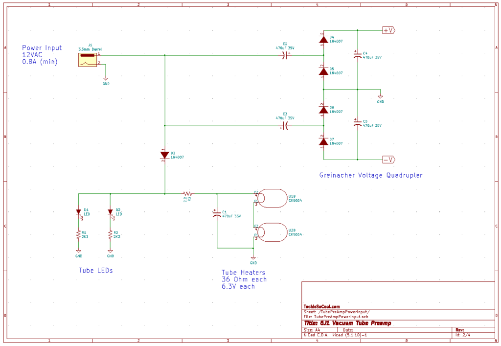
DIY Tube Amp Power Supply
Please note that my reference designators don’t match those on the PCB
The first power supply schematic shows two stages of a Greinacher voltage doubler, which create a voltage quadrupler. The input of 12VAC is boosted to around 48V. Some of the incoming power is diverted, half-wave rectified, and a large cap used to create passable DC to light the LEDs underneath the tubes, and to power the tube heaters.
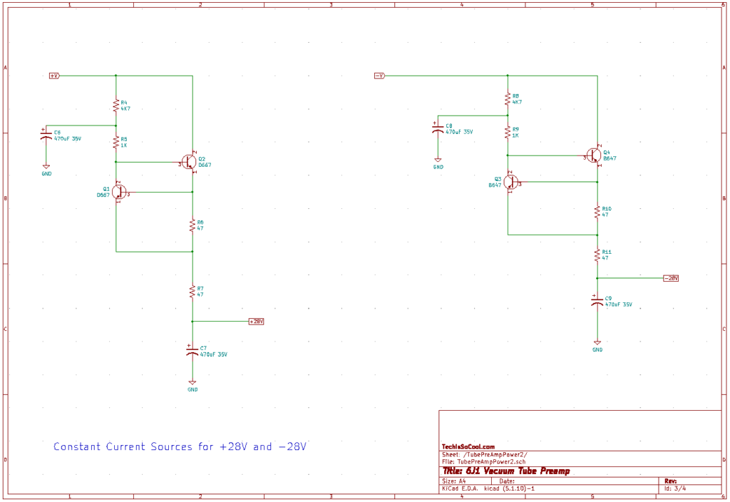
The second sheet takes the output of the voltage multiplier and uses that to supply a positive and negative rail constant current source, or CCS. There are different applications of CCSs in a DIY tube amp. In this case I believe they serve two purposes. One is to help set the bias voltage for the vacuum tubes. The output of the CCSs connect to the grid inputs of the tubes through a large resistor. This allows a small amount of current to help supplement the incoming the audio signal in biasing the tube. I did find a more informed discussion of CCSs and tube amps on wtfamps.com.
Tube Audio Amplifier Section
The third sheet is the audio section of the circuit. Vacuum tubes are essentially amplifiers, so in the simplest amplifier configuration, the tube needs only a the basic supporting circuitry to do the job. Electrons flow from the tube cathode to the tube plate (or anode) in proportion to the current through the grid plate(s) which are physically between the two. Here is a generic tube amplifier configuration. The -VDC can be ground, what matters is the voltage from +VDC to -VDC.
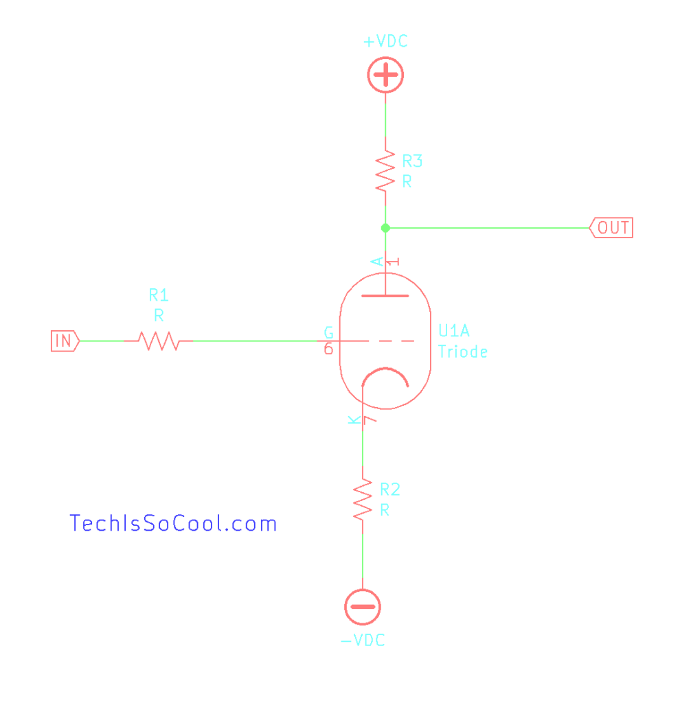
The kit here uses a 6J1 tube, which is a little more complex that the one pictured. It has three grids instead of one. But the way it’s connected in this circuit, it is effectively doing the job of the triode pictured above.
The audio comes in the input jacks. The volume knob directs a portion of the incoming signal to the grid, G1. Again, this is biased with the negative rail through the 470K ohm resistor, adding about 60uA at idle, or a 0V input. The output of the tube is AC-coupled through the 1uF capacitor, and the output voltage is created across the 100K output resistor, which will parallel whatever, presumably much smaller, load you connect to the amplifier.
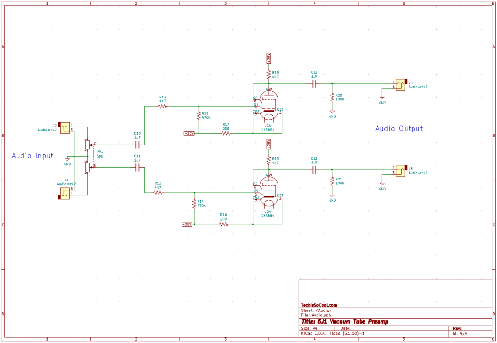
6J1 DIY Tube Amp Schematic
I’m making the schematic available here in hopes that it will be helpful for someone else.
For those who can work with KiCAD files, I’m making the project and schematics available as well. For logistical reasons, they are available on GitHub at https://github.com/TechIsSoCool/DIYTubeAmp
Where to Buy
This links to the DIY Tube Kit on Amazon, and this links to a 12VAC power supply there which will work with the kit. Remember that it’s AC, not DC. You’re less likely to have the right one lying around.
You can find similar DIY tube kits on AliExpress and other hobby sites as well.
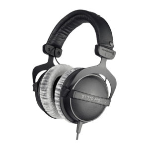
I use these headphones, and I love them! An adapter cable would be needed to connect them to this amplifier.