How to Use the DS3231 Real Time Clock Module with Arduino
I discussed the advantages of using a real-time controller in your Arduino project in a previous post. In this post, I’ll walk you through the basics of how to connect the DS3231 and establish communications with it. If you want to go further, there is another post showing how to build an Arduino alarm clock using the DS3231.
The DS3231 IC has only 8 functional pins. To follow along I’ll assume you have an Adafruit-DS3231 module with a battery, and an Arduino board that has I2C capability built in. I’m using my trusty ATMega2560 to start, which is far more then needed for this project. Once I get the code and hardware where I want it, I can pick the appropriate downsized board to fit it in.
To get things started, connect the DS3231 to the Arduino. You only need to connect 4 lines to start: Power, ground, SCL, and SDA. The DS3231 can be powered from a 3.3V or a 5V supply, so no worries there. It couldn’t be simpler:
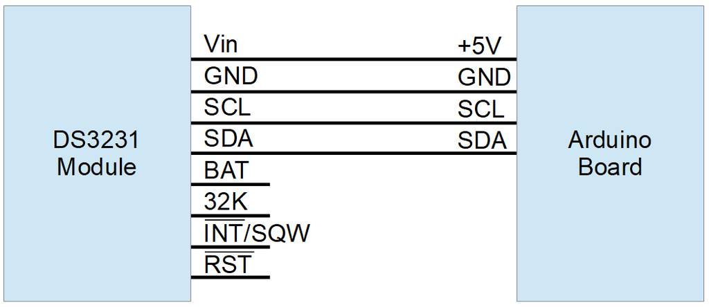
Note: If you’re using an Arduino Feather and the DS3231 RTC FeatherWing Add-on, just plug the Add-on on to the Feather. The proper connections are aligned for you.
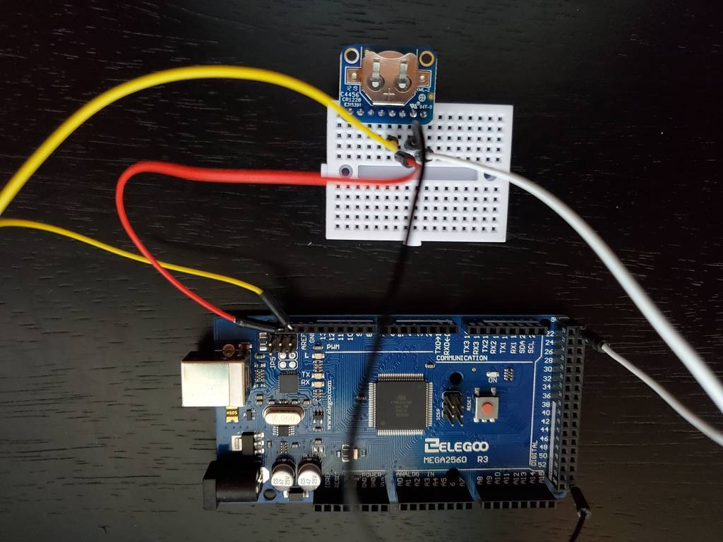
I soldered the header on my module what might be considered upside-down; I wanted the battery reachable, and there’s really nothing to see on the other side. I connected the DS3231 to the Arduino using a little breadboard. In this picture:
- the black wire is ground,
- the white wire is +5V,
- yellow is SDA,
- and red is SCL.
DS3231 Software Libraries
There are a number of libraries available which interface to the DS3231 IC. A Github search for DS3231 is showing 483 listings right now. The most popular one is probably Adafruit’s RTC library. If you want to use Adafruit’s library, install it, include the file in your sketch or open the example, and you’re ready to go.
To install the library, in the Arduino IDE go to Tools > Manage Libraries… and search for ‘RTClib’. Find the match from Adafruit, select the latest version and click Install.
To open the example, select File > Examples > RTClib > ds3231. Open the Serial Monitor (Tools > Serial Monitor) so you can see the output. Verify and Upload the file. If your DS3231 is connected correctly, you’ll see the output of the example sketch on the serial monitor.
For my example though, I’ll be writing my own functions instead of using an existing library.
Communicating With the DS3231 From Arduino
To implement communications with the DS3231 over the I2C bus, I’ll use the Arduino Wire library. That library allows us to write commands and data, and read data from, any I2C device, including the DS3231.
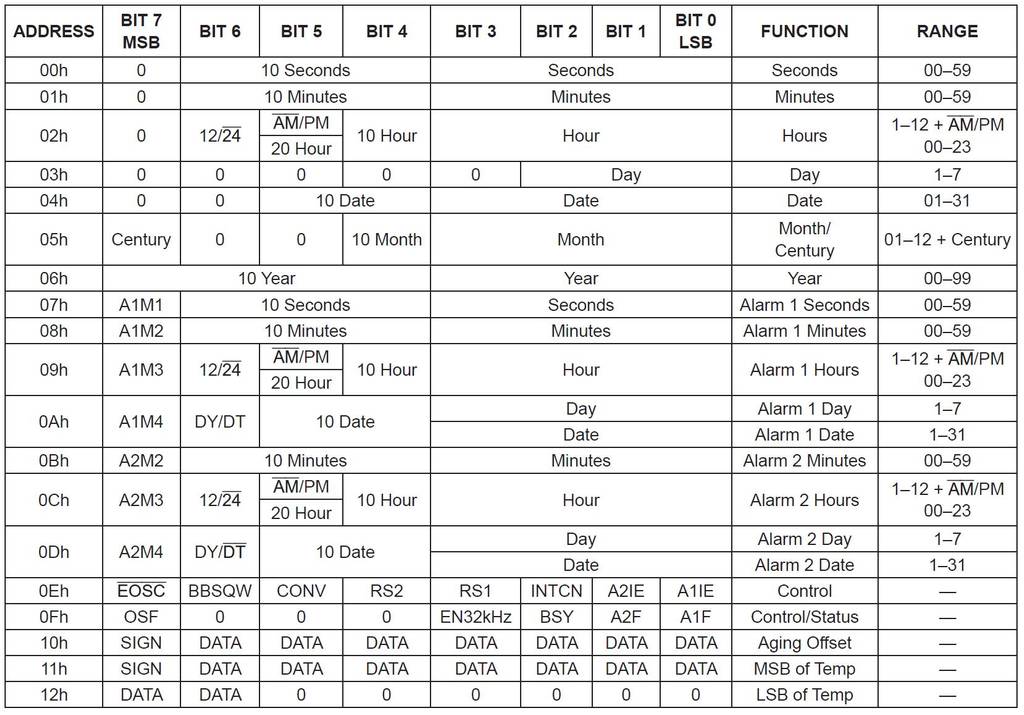
Now, what do we want to write to and read from the device? The datasheet shows that everything interesting in the DS3231 is located in one of 18 registers in the device.
There are two basic communication patterns I’m interested in implementing:
- Write a byte to a specified register
- Read a byte from a specified register
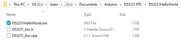
For these direct interface functions, I’m going to put the code in a separate .cpp and .h file outside of my main .ino sketch, but in the same folder. I’m effectively creating my own library for the DS3231 without formally making it a library. In the Arduino IDE select Sketch > Add File… and add the .cpp and .h files to the project. For clarity, here’s the project “structure” I’m using:
In my header file, I want to define the register addresses for each register in the DS3231. And since the address for the DS3231 is hardwired into the IC, I may as well define that too. These are just names for numbers. The names make the code less confusing when you’re trying to read it.
/*TechIsSoCool DS3231 Interface Header */
 //DS3231 I2C Addresses - hardwired in IC
 #define DS3231_READ  0xD1
 #define DS3231_WRITE 0xD0
 #define DS3231_ADDR  0x68

 //DS3231 Registers
 #define DS3231_SECONDS  0x00
 #define DS3231_MINUTES  0x01
 #define DS3231_HOURS  0x02
 #define DS3231_DAY 0x03
 #define DS3231_DATE 0x04
 #define DS3231_CEN_MONTH 0x05
 #define DS3231_DEC_YEAR 0x06
 #define DS3231_ALARM1_SECONDS 0x07
 #define DS3231_ALARM1_MINUTES 0x08
 #define DS3231_ALARM1_HOURS 0x09
 #define DS3231_ALARM1_DAY_DATE 0x0a
 #define DS3231_ALARM2_MINUTES 0x0b
 #define DS3231_ALARM2_HOURS 0x0c
 #define DS3231_ALARM2_DAY_DATE 0x0d
 #define DS3231_CONTROL 0x0e
 #define DS3231_CTL_STATUS 0x0f
 #define DS3231_AGING_OFFSET 0x10
 #define DS3231_TEMP_MSB 0x11
 #define DS3231_TEMP_LSB 0x12
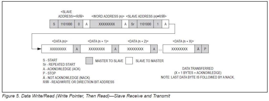
The datasheet indicates that in order to read a value from a specific register, you write the register number to the device, then read a byte back from the device. The byte you read will be the value in the register number you wrote. For example, say register 0x06 (year) holds 5 as its value. To read it I write a 6 to the DS3231, and then ask it to transmit one byte by starting a read operation. It sends back a byte with the value of 5. The Arduino then sends a nack and a stop bit to end the communication process.
Slave Addresses Using Arduino Wire Library
Note that the upper 7 bits of the DS3231’s address are hardwired, and the least significant bit is a 1 to read from the device and a 0 to write to the device.
| b7 | b6 | b5 | b4 | b3 | b2 | b1 | b0 R/ *W bit | in Hex | |
| Reading | 1 | 1 | 0 | 1 | 0 | 0 | 0 | 1 | 0xd1 |
| Writing | 1 | 1 | 0 | 1 | 0 | 0 | 0 | 0 | 0xd0 |
Looking at this, you would be right to think that when you write to the DS32331, you would use address 0xd0, and when you read you would use 0xd1. That’s technically correct – but – I’m using the Arduino Wire library to do the actual I2C communication, and that library takes care of the read/write bit for me. In fact, I must leave that bit off of the address, as the library will append the proper LSB value depending on whether it is performing a read or write operation. So when I make a call from my code to the Wire library, I need to use:
| MSB | LSB | in Hex | ||||||
| implied 0 | 1 | 1 | 0 | 1 | 0 | 0 | 0 | 0x68 |
So if I were to implement the I2C communication
myself, I would use 0xd0 and 0xd1. Since I’m using the Wire library,
I use 0x68 as the IC address. The Wire library will shift the address
left one bit and append the read or write bit to create the 0xd0 or
0xd1 on its own. In fact, digging into the bowels of the Wire
library, in twi.c at lines 174-6, the code that does this is there:
// build sla+w, slave device address + w bit
  twi_slarw = TW_READ;
  twi_slarw |= address << 1;
To build the slave address, the address you pass Wire is shifted left one bit, and a read/write bit is OR’ed into the LSB position. So to use Wire, use the hardcoded address without the read/write bit and add any leading MSB you like (it’s going to be shifted out anyway). That’s important. One could, not just theoretically, spend an afternoon figuring that out. Just sayin’. The upshot for this device is to always use 0x68 as the address, whether reading or writing with the DS3231 and the Wire library. Understanding that this is how Wire works is important for any I2C project you use it with.
Basic Reading and Writing to the DS3231
I need to declare two functions in my header file to use as building blocks. One to read from a register and one to write to a register. I’m going to use the data type ‘uint8_t’ as an 8-bit variable. A char is also 8 bits, but C treats char’s in weird and non-obvious ways so I avoid them unless I need a character.
uint8_t readRegister(uint8_t reg);

void writeRegister(uint8_t reg, uint8_t data);
The readRegister function will take the register to read as its parameter, and return the value in that register. The writeRegister function will accept the register to write to and the data to write into that register as parameters. It doesn’t return anything for now. To be completely robust, it should probably validate that it was successful and return either a boolean pass/fail indication, or the value of the register after the write. For now I’ll just blindly write the value and trust that it got there. If I have problems, this is a potential trouble spot to explore.
It’s time to write some code. I’ll implement each of those functions in the .cpp file.
/*TechIsSoCool DS3231 Interface */
#include "DS3231TISC.h"		//includes the #defines from above

uint8_t readRegister(uint8_t reg){
	Wire.beginTransmission(DS3231_ADDR);	//Sends start bit, slave address, and write bit, waits for ack from device
	Wire.write(reg);						//Sends 8 bits the function was passed, a register address, waits for ack
	Wire.endTransmission();					//Sends the stop bit to indicate end of write
	Wire.requestFrom(DS3231_ADDR,1);		//Sends start, slave address, read bit, waits for ack and one byte, then sends stop
    return Wire.read();						//reads the received byte from the buffer and returns it to whoever called this function
}
void writeRegister(uint8_t reg, uint8_t data) {
	Wire.beginTransmission(DS3231_ADDR);	//Sends start bit, slave address, and write bit, waits for ack from device
	Wire.write(reg);						//Writes the first passed parameter value to the device, hopefully a register address
	Wire.write(data);						//Writes the second passed parameter, the data for that register
	Wire.endTransmission();					//Completes the transaction by sending stop bit
}
The comments might make it a little messy, but I wanted to explain what was happening in each call as it relates to the I2C bus. If you copy that into an editor that will allow for longer lines, it will be clearer.
Now let’s put those functions to use in a simple DS3231HelloWorld sketch. Here’s my DS3231HelloWorld.ino sketch:
//Include the Wire library (again here, for Wire.begin()),
//and include the DS3231_tisc custom code
#include <Wire.h>
#include "DS3231_tisc.h"

void setup() {
  // put your setup code here, to run once:
  Serial.begin(9600);       //Init serial port
  while(!Serial){;}         //Wait for serial port connection
  Serial.println("Hello");  //Show some sign of life
  //Initialize the I2C bus using Arduino Wire library
  Wire.begin();

  //Let's set the time by writing to the registers, any values you like
  writeRegister(DS3231_HOURS,11);
  writeRegister(DS3231_MINUTES,12);
  writeRegister(DS3231_SECONDS,13);
}

void loop() {
  // put your main code here, to run repeatedly:

  //Read back the time and send it to the PC over the USB
  Serial.print("Time is ");
  Serial.print(readRegister(DS3231_HOURS));
  Serial.print(":");
  Serial.print(readRegister(DS3231_MINUTES));
  Serial.print(":");
  Serial.println(readRegister(DS3231_SECONDS));
  delay(500);
}
In the setup loop, I write an arbitrary-but-valid value for each of hours, minutes, and seconds. In the main loop I read those registers back and send them back to the PC over the USB port. If you run this now, this is what you see on the Serial Monitor:
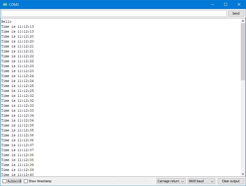
The Arduino sends back ‘Hello’, then starts to read the registers and print the time. I’m checking the time just under twice a second (500ms + time to I2C read and Serial.print in each loop), so I get one or two readings during the same second. The time values are incrementing. But look at the values that are coming back – they’re jumping way too much! It jumps from 11:12:13 to 11:12:20, that’s 7 seconds, which did not really pass in between those samples. What’s going on?
BCD / Decimal Conversion
Well, there’s one more gotcha to deal with before sending and receiving data with the DS3231. Back to the datasheet. The contents of different registers are encoded in different formats. They aren’t just straight values you can read and use. Actually, this is done to make them more useful, but in a different way than I am using them here. The time-related registers are encoded in binary-coded-decimal, or BCD format. BCD is very handy when trying to display numbers when you don’t have a microcontroller in your design. If you were using logic gates to display the time on 7-segment LED displays for example, having BCD data would be a huge help, there’s even a logic chip that does that specific conversion.
In BCD format, each nibble (4 bits) represents one digit in the number, and has the 0-9 value for that digit. The number 123 would be represented in three nibbles, 0001, 0010, and 0011. Literally ‘1’, ‘2’, and ‘3’. Think back to elementary school days, it’s a 1 in the hundred’s place, a 2 in the tens place, and a 3 in the ones place. It’s not 123, it’s a 1 and a 2 and a 3. We have to convert our data to and from BCD as we write and read the time registers.
This functionality is fundamental and will be used every time with this chip regardless of application, so it goes in the cpp file. Here’s how:
uint8_t _toBcd(uint8_t num)
{
	uint8_t bcd = ((num / 10) << 4) + (num % 10);
	return bcd;
}

uint8_t _fromBcd(uint8_t bcd) {
	uint8_t num = (10*((bcd&0xf0) >>4)) + (bcd & 0x0f);
	return num;
}
To convert to BCD, take the number and divide it by ten. This will give you the whole number, without remainder, of times the number can be divided by ten. That’s the tens value. Shift it to the upper nibble, 4 bits left. Then modulo the number by ten, which gives you the remainder of dividing by ten (so a number from 0-9). This is the ones value, OR the ones value into the four 0 bits that got put there when when the left shift was performed. Now the tens digit is in the upper nibble, and the ones digit is in the lower nibble. Done deal.
Converting from BCD to decimal, the logic looks like this.
//Shift the upper nibble down to the lower nibble, filling with zeros.
//That's the tens value.
uint8_t tens = bcd >> 4;
//Using the original BCD value, mask off the upper nibble by ANDing it
//with 0's, preserve the lower nibble by ANDing it with ones.
//That gives the value of only the lower nibble, so it's the ones value
uint8_t ones = bcd & 0x0f;
//Multiply the tens value by 10, add the ones, and there's your number.
uint8_t num = (10 * tens) + ones;
return num;
Substitute the individual calculations for ‘tens’ and ‘ones’ in the last formula, and you get the line of code in my function. It might look fancy, but it’s second grade math.
OK, now I can convert to and from BCD, and that needs to happen when I read and write time values, so those functions need to be updated to use the conversion. Since BCD encoding is used only in time-related registers, I’m going to make renamed copies of readRegister and writeRegister which are only for time-related registers and do the BCD conversions. That way I still have functions for raw data access, and I have functions I can use for time-related transactions. I just need cut & paste copies of the first two functions, with new names and some strategically placed BCD conversions. This gets added to the .cpp file:
uint8_t readTimeRegister(uint8_t reg){
  Wire.beginTransmission(DS3231_ADDR);
  Wire.write(reg);
  Wire.endTransmission();
  Wire.requestFrom(DS3231_ADDR,1);
  return _fromBcd(Wire.read());
}

void writeTimeRegister(uint8_t reg, uint8_t data) {
  Wire.beginTransmission(DS3231_ADDR);
  Wire.write(reg);
  Wire.write(_toBcd(data));
  Wire.endTransmission();
}
Note that only the data values get converted, not the register numbers or device address. This creates some housekeeping: Add prototypes to the header file, which now looks like this:
/*************************************************************************
***  TechIsSoCool.com DS3231 Interface
***  DS3231_tisc.h
***	 Constants and function prototypes
**************************************************************************/
//DS3231 I2C Addresses - hardwired in IC
#define DS3231_READ  0xD1
#define DS3231_WRITE 0xD0
#define DS3231_ADDR  0x68

//DS3231 Registers
#define DS3231_SECONDS      0x00
#define DS3231_MINUTES      0x01
#define DS3231_HOURS      	0x02
#define DS3231_DAY        	0x03
#define DS3231_DATE       	0x04
#define DS3231_CEN_MONTH    0x05
#define DS3231_DEC_YEAR     0x06
#define DS3231_ALARM1_SECONDS 0x07
#define DS3231_ALARM1_MINUTES 0x08
#define DS3231_ALARM1_HOURS   0x09
#define DS3231_ALARM1_DAY_DATE  0x0a
#define DS3231_ALARM2_MINUTES 0x0b
#define DS3231_ALARM2_HOURS   0x0c
#define DS3231_ALARM2_DAY_DATE  0x0d
#define DS3231_CONTROL      0x0e
#define DS3231_CTL_STATUS   0x0f
#define DS3231_AGING_OFFSET 0x10
#define DS3231_TEMP_MSB     0x11
#define DS3231_TEMP_LSB     0x12
/*** Prototypes ***/
//Reads from register, returns register value
uint8_t readRegister(uint8_t reg);
//Writes data to register
void writeRegister(uint8_t reg, uint8_t data);
//Reads from register, returns register value, accounts for BCD
uint8_t readTimeRegister(uint8_t reg);
//Writes data to register, accounts for BCD
void writeTimeRegister(uint8_t reg, uint8_t data);
//decimal -> BCD conversion
uint8_t _toBcd(uint8_t num);
//BCD -> decimal conversion
uint8_t _fromBcd(uint8_t bcd);
And I need to update the main sketch to use the new functions.
//Include the Wire library (again here for Wire.begin())
//and the DS3231_tisc code
#include <Wire.h>
#include "DS3231_tisc.h"


void setup() {
  // put your setup code here, to run once:
  Serial.begin(9600);       //Init serial port
  while(!Serial){;}         //Wait for serial port connection
  Serial.println("Hello");  //Show some sign of life
  //Initialize the I2C bus using Arduino Wire library
  Wire.begin();

  //Let's set the time by writing to the registers, any values you like
  writeTimeRegister(DS3231_HOURS,11);
  writeTimeRegister(DS3231_MINUTES,12);
  writeTimeRegister(DS3231_SECONDS,13);
}

void loop() {
  // put your main code here, to run repeatedly:

  //Read back the time and send it to the PC over the USB
  Serial.print("Time is ");
  Serial.print(readTimeRegister(DS3231_HOURS));
  Serial.print(":");
  Serial.print(readTimeRegister(DS3231_MINUTES));
  Serial.print(":");
  Serial.println(readTimeRegister(DS3231_SECONDS));
  delay(500);
}
With the conversions in place, recompile and everything looks much better:
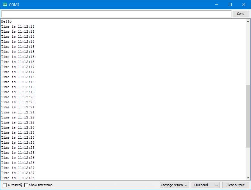
The time is ticking away in order now, I’m writing the proper values to the registers, and interpreting the values correctly.
Note: I didn’t include the BCD conversion in the readRegister() and writeRegister() functions directly because not every register is encoded in BCD, just the time-related ones. The aging offset and temperature registers are encoded in two’s complement form, which requires a different conversion. The Control and Control/Status registers are collections of bitflags, numerical values don’t really apply. The various bits need to be set in a variable before writing it to the register, and interpreted individually when read.
This post is getting lengthy. I wanted to cover communications between Arduino and the DS32331 Real Time Clock at a very elemental level for anyone seeking to understand how to connect these two devices. Any application that you create with the DS3231 can build on the fundamental blocks created here. It all comes down to reading and writing the registers. I didn’t want to muddy the waters with the specifics of a particular display or input devices, so I just used the Serial Monitor and hardcoded a time value to set the clock. In subsequent posts I’ll build on this logic to create a more practical clock, with display, buttons, alarms, the whole package.
If you’re new to Arduino, electronics, programming, or communicating with I2C devices, I hope this proved helpful.
Here are some handy related links:
Arduino Mega2560 R3 board by Elegoo – a clone, but is working great for me, and inexpensive
Adafruit DS3231 Precision RTC Breakout – Get the Adafruit version, this is not the part to save money on.
CR1220 Batteries – for continued timekeeping when not powered externally
Breadboard – If you don’t have any, here’s some inexpensive ones
Breadboard Jumper Wires – The kinds with the connectors are nice to have, get an assortment like this
DS3231 Datasheet – All the details of the IC
Adafruit’s DS3231 Learn page – more info and handy links, includes Circuit Python links if that’s your thing.
Arduino’s Wire library reference – information about compatible boards and functions made available by the library. The code itself is in your \Documents\ArduinoData\packages\arduino\hardware\avr\1.8.2\libraries\Wire\ folder assuming you’ve added the library in the IDE.
Happy creating – See you next, er, time!
Congratulations, great instructions. Really did help!
This is just what I was looking for!
Your hard work and explanations
are greatly appreciated!!
This is great. I’m making a binary clock, so directly reading the binary memory contents of the chip appeals to me. I’ve ditched the pre made libraries and am using bits of code from here – its very useful – thanks very much….
This looks like what I’m after for a project…. thanks!